

Details
Technical data
| General Specifications | |
| Sensing distance | 70…1000mm |
| Adjustment range | 90…1000mm |
| Unusable area | 0…70mm |
| Standard target plate | 100mm×100mm |
| Transducer frequency | About 255kHz |
| Response delay | About 125ms |
| Indicators/Operating means | |
| LED blue | Power on |
| LED yellow |
indication of the switching state Flashing:program function object detected |
| LED red |
permanently red: Error Red,flashing:program function,object not detected |
| Electrical specifications | |
| Operating voltage U B | 10…30VDC,ripple10%ss |
| No-load supply current | ≤45mA |
| Output | |
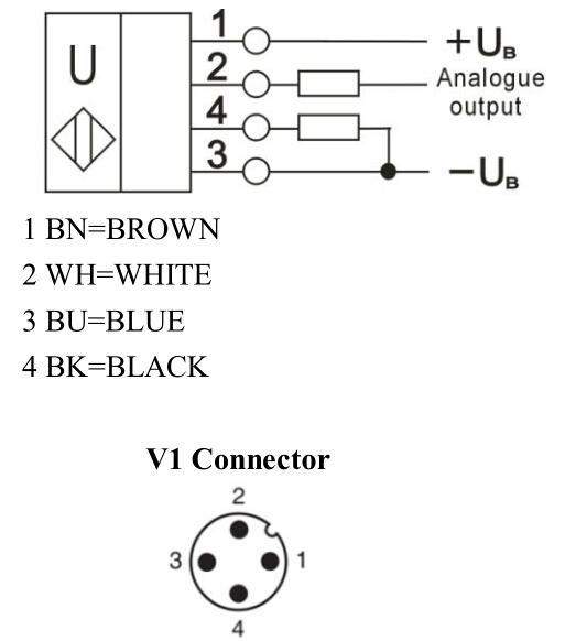
| Output type | 1 analogue output 4…20mA |
| Resolution | 0.35mm at max.sensing range |
|
Deviation of the characteristic curve |
±1% of full-scale value |
| Repeat accuracy | ±0.1% of full-scale value |
| Load impedance | 0…300 Ohm |
| Temperature influence | ±1.5% of full-scale value |
| Ambient conditions | |
| Ambient temperature | -25…70℃ |
| Storage temperature | -40…85℃ |
| Mechanical specifications | |
| Protection grade | IP67 |
| Connection | Connector M12x1,4-PIN |
| Material Housing | brass,nickel-plated |
| Transducer |
epoxy resin/hollow glass sphere mixture; Polyurethane foam |
| Weight | 60g |
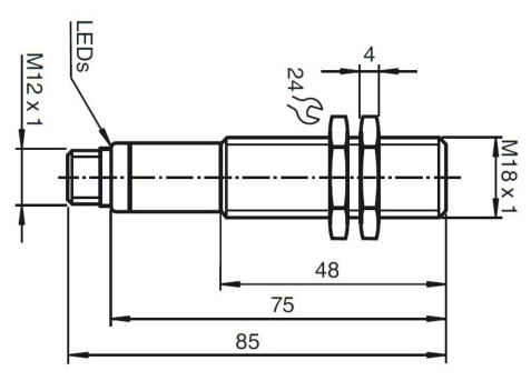
Dimension
Connection
External synchronization
The sensor can be synchronised by the external application of a square wave voltage. A synchronisation pulse at the synchronisation input starts a measuring cycle. The pulse must have a duration greater than 100 μs. The measuring cycle starts with the falling edge of a synchronisation pulse. A low level > 1 s or an open synchronisation input will result in the normal operation of the sensor. A high level at the synchronisation input disables the sensor. Two operating modes are available:1. Multiple sensors can be controlled by the same synchronisation signal. The sensors are synchronised.
2. The synchronisation pulses are sent cyclically to individual sensors. The sensors operate in multiplex mode.
Internal synchronization
The synchronisation connections of up to 5 sensors capable of internal synchronisation are connected to one another. When power is applied, these sensors will operate in multiplex mode.The response delay increases according to the number of sensors to be synchronised. Synchronisation cannot be performed during TEACH-IN and vice versa. The sensors must be operated in an unsynchronised manner to teach the evaluation limits.
Note
If the option for synchronisation is not used, the synchronisation input has to be connected to ground (0V) or the sensor has to be operated via a V1 cable connector (4-pin).View more about UB1000-18GM75-I-V1 on main site